Our Experts: Jaime Diez Merida (LMU) and Dmitri Efetov (LMU)
Here we present the basis of the protocol developed at LMU to fabricate magic angle twisted bilayer graphene (MATBG) with a angular alignment of 1.1 deg +/- 0.1 deg. The details of the protocol can be found in their recent ArXiv
Preparation of 2D crystals
Exfoliation: to obtain large areas graphene it is recommended to use the heating technique (see Stacking and Twisting section), contrary to obtain graphite that is easily picked up from the substrate it is better to perform a second exfoliation without using O2 plasma.
Flake selection: Selected flakes should have no tape residues, nor step-terraces and should be well isolated from nearby bulky flakes which typically cause problems during the stacking process. Then, there are certain constraints to consider for the different materials.
i) Graphene flakes – these should be at least twice as large as the desired device size.
ii) BN flakes – should fully encapsulate the graphene and are chosen to be 10 – 20 nm thick, which is considerably thin. Thinner hBN flakes are considerably more elastic than thicker flakes, which makes the stacking process much smoother and may generally help in the strain relaxation within the hetero-structure. It also aids to avoid unexpected rapid movements or “jumps” in the stamp during the stacking. Keep the flake thicker than 5 nm to avoid breaking it during transfer. The hBN which will be picked up first should have at least one sharply defined edge
iii) Graphite flakes – these are chosen to be ⁓ 2 – 4 nm thick, 3 – 6 μm wide and 10 – 15 μm long. The width is chosen such that in the final transport devices the arms of the Hall bars, which extend beyond the width of the device, can be gated away from the charge neutrality point using the highly doped Si substrate, which helps minimize the contact resistance. The bottom gate needs to be longer than graphene, such that it can be easily contacted during the lithography process.
Next step is to create two graphene sheets with identical crystallographic orientation. For this you can follow any of the cutting techniques described in the Stacking and Twisting section. That ensures that both sheets, used to compose the twisted bilayer device, have exactly the same initial crystallographic orientation prior to the rotation of the layers.
Twist-angle locking
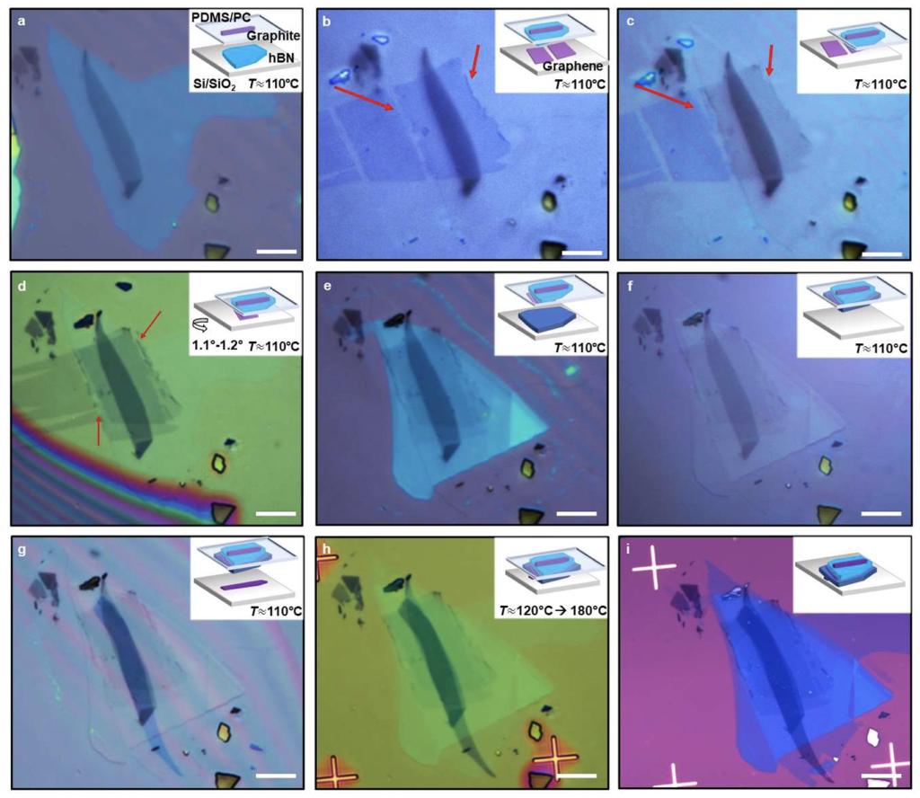
The first picked-up hBN is generally chosen to have at least one sharp edge, which will be used as an anchor, to which we clamp the edges of the two graphene flakes, which were defined in the graphene cutting process. The edge between the 2D crystals fold over each over and interlock over a length of ⁓ 1 μm, which is visible in the optical images (see Fig. b-d), and so restrict any further relative motion between them. This significantly increases the probability to retain a twistangle of the TBG stack close to the magic-angle.

The entire pick-up process is done by fixing the stage temperature to T ⁓ 100 – 120 °C. The lamination on the flakes is done at constant T, and the approaching of the crystals is done entirely by hand using the z-micromanipulator on the transfer stage.
Once de device is completed, it is deposited on a SiO2 chip, this is done in a range of temperature of 120-150 degrees. The wavefront is moved very slowly over the stack to push away all the remaining bubbles. Once the full stack is in contact with the SiO2, the wave front is moved ca. 200 μm further from the stack. Now the stage temperature T is raised slowly up to 180 °C. As the T approaches the glass transition temperature, Tg, of the PC of ⁓ 147°C 42 the PC detaches from the PDMS film and at a T far beyond the glass transition ⁓ 180 °C, the PC completely melts.
Strategies to enhance twist-angle homogeneity
Using clean stamps and flakes – We make sure we use an area of the stamp which is clean and larger than the largest flake to be used.
Using thin hBN flakes – We use thin hBN (10 – 20 nm), which is considerably more elastic than thicker flakes, and makes the stacking process much smoother and may generally help in the strain relaxation within the hetero-structure.
Cleaning surrounding areas – We clean the area surrounding the desired flake
High temperature colamination process – The entire stacking process is done at high T ⁓ 100 – 120 °C as this serves to improve the self-cleaning properties of the van der Waals interfaces during the stacking process and to enhance bubble mobility in all the pick-up steps3
